- Do not open the housing: loaded spring
- Hold MEMOLUB® down during manual checks
- Leq <70 dB
- Use MEMOLUB® only for greasing machinery
- Use only lubricant cartridges and batteries recommended by the manufacturer


Memolub® Visio KNOWLEDGE BASE
Dimensions
Standard
120cc I 4oz

Mega
240cc I 8.1oz

Giga
480cc I 16.2oz

OIL R-500
500cc I 16.9oz

Precautions

INSIDE THE BOX

MEMOLUB® VISIO Pump

MEMOLUB® Housing Kit

MEMOLUB® VISIO Base
Settings & Feedback
FREQUENCY SETTINGS
| WHEEL POSITION | DOSING PERIODICITY | MAX. DAILY OUTPUT* | REFILLING FREQUENCY VS. CARTRIDGE CONTENT (120CC) | REFILLING FREQUENCY VS. CARTRIDGE CONTENT (240CC) | REFILLING FREQUENCY VS. CARTRIDGE CONTENT (480CC) |
|---|---|---|---|---|---|
| 0 | - | ||||
| 1 | 24 hours | 0.6 cc/day | 6 months | 12 months | 24 months |
| 2 | 16 hours | 0.9 cc/day | 4 months | 8 months | 16 months |
| 3 | 12 hours | 1.2 cc/day | 3 months | 6 months | 12 months |
| 4 | 8 hours | 1.8 cc/day | 2 months | 4 months | 8 months |
| 5 | 4 hours | 3.6 cc/day | 1 month | 2 months | 4 months |
| 6 | 2 hours | 7.2 cc/day | 0,5 months | 1 month | 2 months |
| 7 | 1 hour | 14.4 cc/day | 0,25 month | 0,5 month | 1 month |
| 8 | 1/2 hour | 28.8 cc/day | - | 0.25 month | 0.5 month |
| 9 | 1/4 hour | 57.6 cc/day | - | 0.25 month | |
*Maximum daily output without stroke washers.
Please consider your lubricant's expiry date when opting for long cartridge lifetimes (16 & 24 months).
VOLUME SETTINGS [cc/day]
By using stroke washers you can adjust the amount of lubricant discharged per pumping cycle.
| NUMBER OF STROKE WASHERS | WHEEL POSITION | |||||||||
|---|---|---|---|---|---|---|---|---|---|---|
| 0 | 1 | 2 | 3 | 4 | 5 | 6 | 7 | 8 | 9 | |
| - | N/A | 0.6 cm³ | 0.9 cm³ | 1.2 cm³ | 1.8 cm³ | 3.6 cm³ | 7.2 cm³ | 14.4 cm³ | 28.8 cm³ | 57.6 cm³ |
1x 
|
N/A | 0.56 cm³ | 0.84 cm³ | 1.12 cm³ | 1.69 cm³ | 3.4 cm³ | 6.7 cm³ | 13.5 cm³ | 27 cm³ | 54 cm³ |
1x  + +
|
N/A | 0.52 cm³ | 0.79 cm³ | 1.04 cm³ | 1.58 cm³ | 3.15 cm³ | 6.3 cm³ | 12.6 cm³ | 25.2 cm³ | 50.4 cm³ |
|
2x +
|
N/A | 0.49 cm³ | 0.73 cm³ | 0.98 cm³ | 1.46 cm³ | 2.92 cm³ | 5.85 cm³ | 11.7 cm³ | 23.4 cm³ | 46.8 cm³ |
|
3x +
|
N/A | 0.45 cm³ | 0.67 cm³ | - | 1.35 cm³ | 2.7 cm³ | 5.4 cm³ | 10.8 cm³ | 21.6 cm³ | 43.2 cm³ |
|
4x +
|
N/A | 0.41 cm³ | - | 2.47 cm³ | 4.95 cm³ | 9.9 cm³ | 19.8 cm³ | 39.6 cm³ | ||
|
5x +
|
N/A | 0.37 cm³ | - | 2.2 cm³ | 4.5 cm³ | 9 cm³ | 18 cm³ | 36 cm³ | ||
|
6x +
|
N/A | 0.34 cm³ | - | 2.02 cm³ | 4.05 cm³ | 8.1 cm³ | 16.2 cm³ | 32.4 cm³ | ||
*The circlip must always be added on top of the washers.
The circlip must always be added on top of the washers.
VISUAL FEEDBACK
| COLOR | SITUATION |
|---|---|

|
The gearbox motor is damaged or broken. The tube might be clogged. |

|
The battery is low. |

|
Abnormal temperature is detected or there is an issue with the pump. |

|
The testrun activation via the touchpad was successful. |
REMOTE INSTALLATION DISTANCES
| TYPE OF INSTALLATION | MAXIMUM DISTANCE |
|---|---|
| Single point | 8m |
| Multipoint with 2 outlets | 6m |
| Multipoint with 4 outlets | 6m |
Specifications
Electric Specifications
| MEMOLUB® VISIO | |
|---|---|
| Power Source | Battery |
| Voltage | 4.5V DC (3x1.5V DC AA) |
| Short circuit protection | Yes |
| Stroke duration | 8 seconds |
| Minimum stroke interval | 15 minutes |
INSTALLATION GUIDELINES
DIRECT INSTALLATION
-
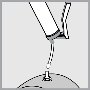
1
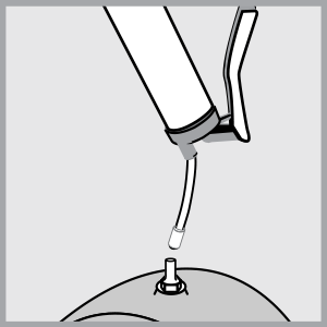
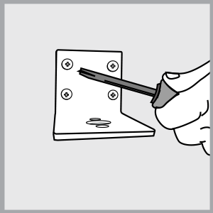
Prime lube point and remove nipple.
-
2
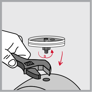
Install VISIO Base using a strong threadlocker (BSP 1/4).
-
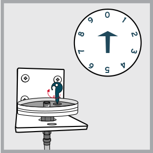
3
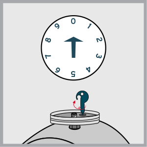
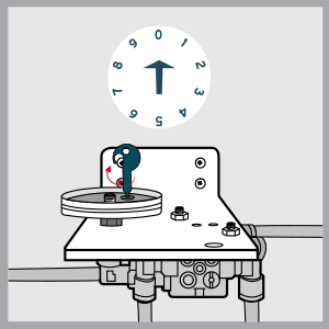
With setting key, choose wheel position according to "Settings" table above.
-
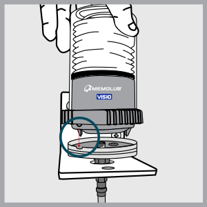
4
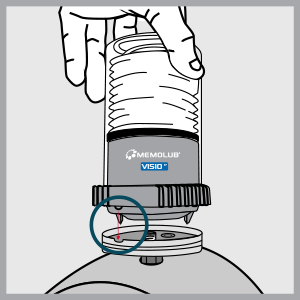
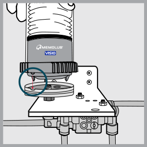
Align the pin of VISIO Module with the notch of VISIO Base.
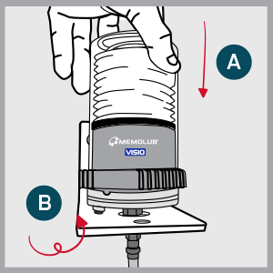
-
5
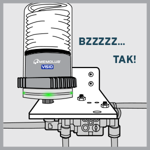
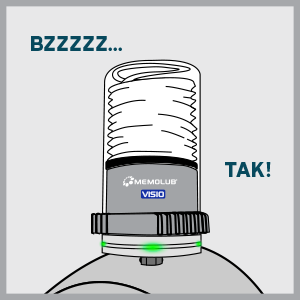
Screw tightly keeping the assemly aligned.
-
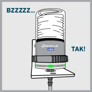
6

VISIO initializes, flashes each color on, and makes one expulsion. Green lights confirm normal operation.


REMOTE INSTALLATION
-
1

Prime lube point and remove nipple.
-
2
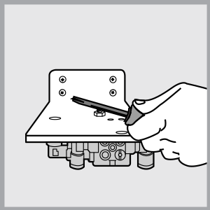
Secure the mounting bracket.
-
3
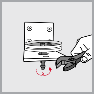
Install VISIO Base and F1/4 fitting on bracket using a strong threadlocker.
-
4
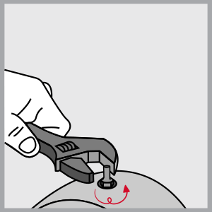
Install BSP 1/8 fitting on lube point.
-
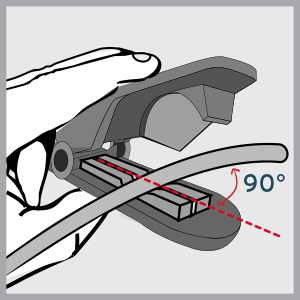
5
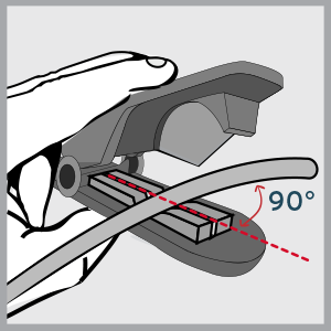
Cut hose to required size.
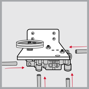
-
6
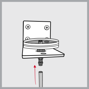
Insert hose into bracket's quick fitting.
-
7
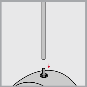
Insert hose into lube point's quick fitting.
-
8
With setting key, choose wheel position according to "Settings" table above.
-
9
Align the pin of VISIO Module with the notch of VISIO Base.
-
10
Screw tightly keeping the assembly aligned.
-
11
VISIO initializes, flashes each color on, and makes one expulsion. Green lights confirm normal operation.


MULTIPOINT INSTALLATION
-
1
Prime lube point and remove nipple.
-
2
Secure the mounting bracket.
-
3

Install VISIO Base and F1/4 fitting on bracket using a strong threadlocker.
-
4

Install BSP 1/8 fitting on lube point.
-
5
Cut the hoses to required size.
-
6
Insert hoses into bracket's quick fittings.
-
7

Insert hoses into lube points' quick fittings.
-
8
With setting key, choose wheel position according to "Settings" table above.
-
9
Align the pin of VISIO Module with the notch of VISIO Base.
-
10

Screw tightly keeping the assembly aligned.
-
11
VISIO initializes, flashes each color on, and makes one expulsion. Green lights confirm normal operation.


CARTRIDGE REPLACEMENT GUIDELINES
-
1
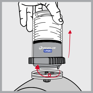
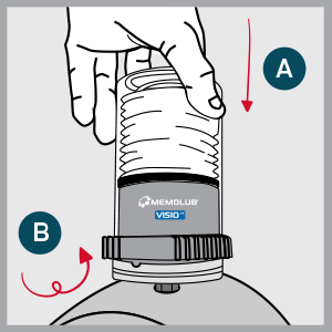
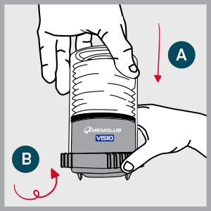
Remove VISIO Module from VISIO Base.
-
2
Open VISIO Module (fingers on ribs).
-
3
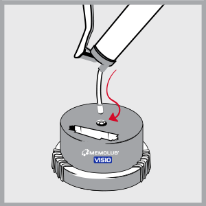
Prime VISIO Pump.
-
4
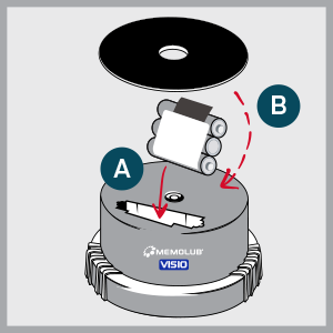
Insert new battery pack and seal. NOTE: the battery seal can be removed for 480cc cartridges
-
5
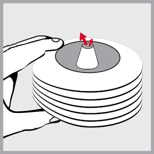
Squeeze air out of the cartridge.
-
6
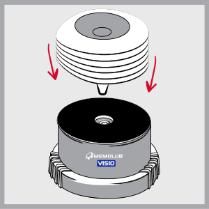
Replace the cartridge on VISIO Pump.
-
7
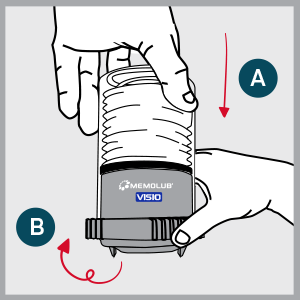
Close and lock VISIO Module (fingers on ribs).
-
8
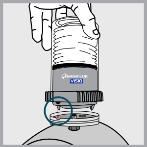
Align the pin of VISIO Module with the notch of VISIO Base.
-
9
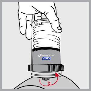
Screw tightly keeping the assembly aligned.
-
10
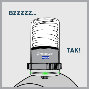
VISIO initializes, flashes each color on, and makes one expulsion. Green light confirms proper functioning.


CHECK FUNCTION
-
1
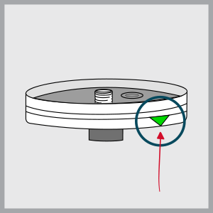
Locate the green triangular label indicating touchpad
-
2
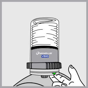
Keep your fingers under VISIO Base, below the triangular sign. Blinking of the 4 green lights confirm activation of the touchpad.
-
3
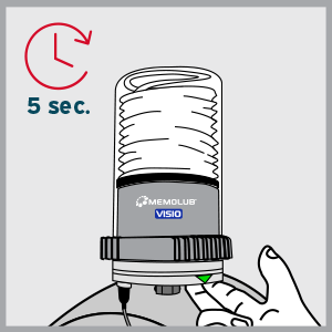
Once the total touch duration has reached 5 sec, the 4 green lights are turned on simultaneously for 1s.
-
4
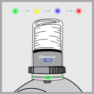
VISIO initializes, flashing each color on successively.
-
5
VISIO makes 1 expulsion.
-
6

After scanning all parameters, VISIO flashes green lights in case of normal operation. For any other colors, please refer to the FAQ section.


FAQ
-
Nothing happens after screwing the module on the base.
- The pin of the module is possibly not proper aligned with the notch of the base. Unscrew the module from the base, align correctly and screw it again.
- VISIO Module is not tightly screwed to VISIO Base. Turn it clockwise until stop.
- There is possibly no battery inside the module. Insert 3x 1,5 VDC AA batteries to resolve the issue.
- There is possibly something obstructing the communication between the base and the module contacts. Unscrew the module from the base, remove any dust or obstacles from the base and the module contacts and screw back together tightly.
-
The touchpad does not work after initialisation was completed successfully.
Your MEMOLUB® VISIO possibly initialized in an unstable environment. Unscrew the base from the module and screw again to reset the system. Wait until one expulsion is performed and you observe green lights, indicating the initialization is complete.
-
The red lights are blinking periodically.
- There is possibly a too high back pressure present in the system. Inspect your downstream piping to remove any clogging or jam. Activate the touchpad and check for at least 2 expulsions if the systems operate fine.
- There is possibly something obstructing the communication between the base and the module contacts. Unscrew the module from the base, remove any dust or obstacles from the base and the module contacts and screw back together tightly.
- The motor is broken. Replacement of the module is necessary.
- There is possibly a too high back pressure present in the system. Inspect your downstream piping to remove any clogging or jam. Activate the touchpad and check for at least 2 expulsions if the systems operate fine.
-
The yellow lights are blinking periodically.
- There is possibly something obstructing the communication between the base and the module contacts. Unscrew the module from the base, remove any dust or obstacles from the base and the module contacts and screw back together tightly.
- The batteries are empty. Replacement of the battery pack is necessary.
- There is possibly something obstructing the communication between the base and the module contacts. Unscrew the module from the base, remove any dust or obstacles from the base and the module contacts and screw back together tightly.
-
The blue lights are blinking periodically.
- The cartridge is possibly out of grease. Replacement of the cartridge is necessary.
- The system is not primed. Prime the system using a manual grease pump.
- The system is operating out of its minimum and maximum temperature range. Please make sure the system is operating within the recommended temperature range.
- The cartridge is possibly out of grease. Replacement of the cartridge is necessary.
REGULATORY INFORMATION
| SYMBOL | DESCRIPTION |
|---|---|

|
This product is compliant with Directives 2006/42/EC (Machinery). The relevant Declaration of Conformity is available here. |

|
This product is compliant with UK regulations 2008 No. 1597 (Supply of Machinery). The relevant Declaration of Conformity is available here. |

|
This product is compliant with customs union technical regulation TR CU 010/2011 (safety of machines and equipment). The relevant Declaration of Conformity is available here. |

|
The WEEE symbol is attached to the product in compliance with the EU directive 2012/19/EU on Waste Electrical and Electronic Equipment (WEEE). It is intended to deter the improper disposal of this product and to promote reuse and recycling. |

|
The packaging material can be recycled. Please arrange for the environmental appropriate disposal of the packaging. |


Memolub® Visio
- Visual alerts
- Battery powered
- 25 bar ejection pressure
- Up to 12 lubrication points simultaneously
- Remote installation up to 8m
- 62 frequency settings